Originally developed for estimating leakage rates through valves to flare in oil refineries and offshore platforms, acoustic emission technology is also finding use in other process industries such as power generation, nuclear, chemicals and pharmaceuticals, says Tim Bradshaw
The detection of leaks by acoustic methods was used well before the technology of acoustic emission (AE) was applied elsewhere. However, the equipment that was available was susceptible to noise from sources other than leaks, such as that from normal plant operation and the surrounding environment. As the AE industry grew in other areas, technology became available which meant that the problems of environmental noise could be largely overcome.
A trials programme carried out by BP between 1982 and 1984 selected the AE method as most promising for development as a method of quantifying leakage through valves. The field development programme lasted six years and involved removing more than 800 valves from service that had been identified as leaking, and retesting these in the laboratory to build up a correlation between physical loss and acoustic signal level.
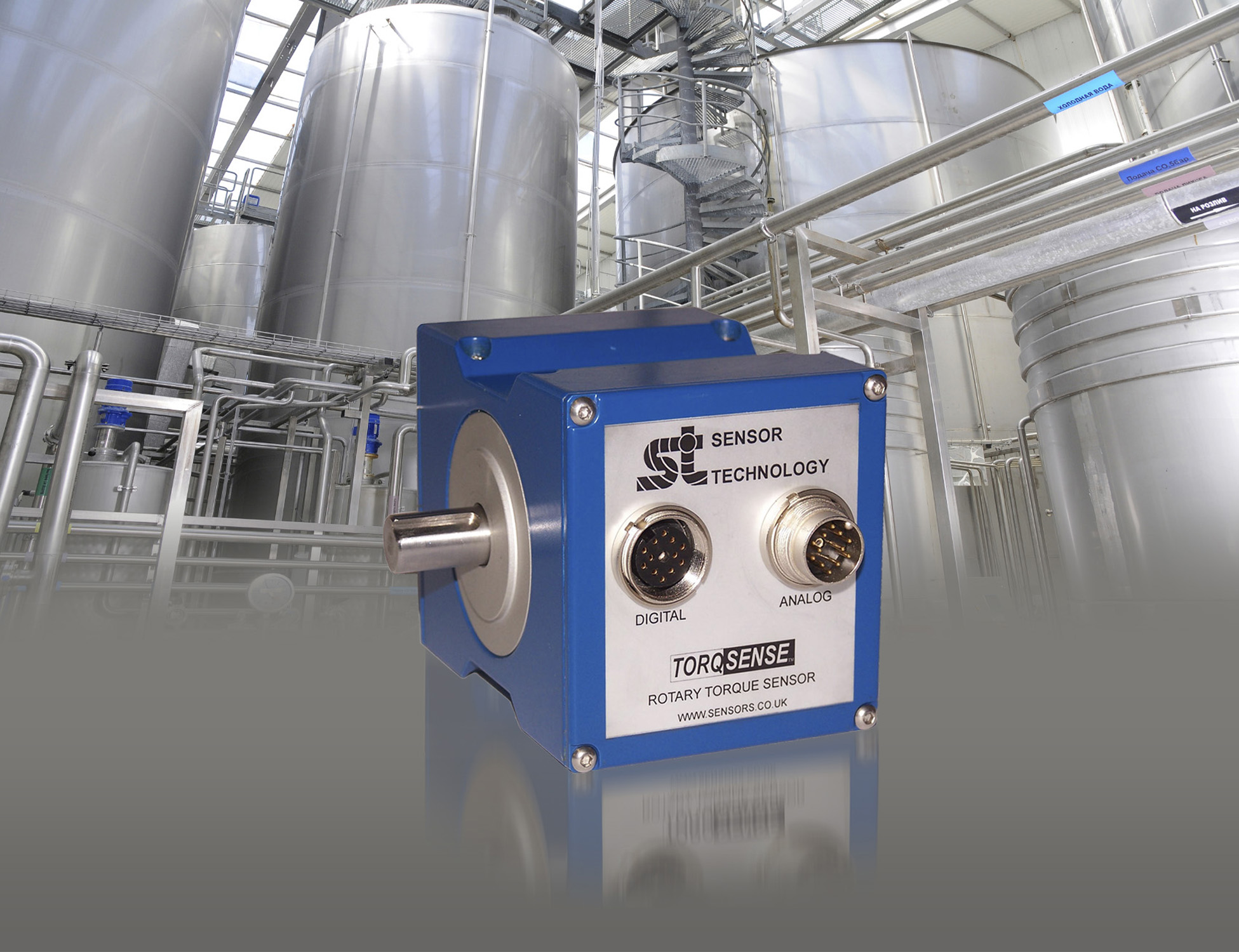
Following this, a 'best fit' correlation was developed so that the technology could be easily applied. Factors having a significant effect on the acoustic signal level include valve type, size, and differential pressure. This development was followed by the commissioning of a new instrument able to make accurate field measurements to make practical use of the database. The new instrument, the VPAC II from Mistras Group, is intrinsically safe, portable and simple to use by virtue of all the measurement functions being automatic. This instrument together with the 'VPAC' Valve Leak Technology Package, as the quantification method is known, has become widely used in the oil and gas industry for the identification and estimation of through-valve gas losses, thus enabling cost effective operational and maintenance decisions to be made quickly and easily without plant disruption, and by personnel with just one hour of training.
Detection principle
The source of the acoustic emissions should be considered initially. These are generated by a fluctuating pressure field that is associated with turbulent flow of the fluid at the leak site. The conditions for turbulent flow are met when the inertial effects of the fluid flow overcome the viscous drag; the ratio of the former to the latter is defined as the Reynolds number. Turbulence has been found to commence when the value for the Reynolds number is between 103 and 104. Acoustic Emission, therefore, is an effective method for detection of through valve leaks where the velocity across the leak is sufficiently high with respect to the size of the leak orifice to produce a Reynolds number in this region.
Quantification
The calculation to deduce the flow rate in a cylindrical orifice would be simple. However, this is far from the real world situation where a leak is likely to be anything but a cylindrical orifice and is also likely to be made up from a number of smaller leaks around the entire valve seat. As a result, an alternative method of correlating the AE received and the flow rate through the leak was required. This was achieved empirically by testing 800 valves in the field and repeating the tests with the valves removed to a flow rig. Valves in the size range 1 - 18-in and of a range of types were used in this exercise and a database of results was compiled from which a predictive equation was derived. It is this predictive equation that allows the quantification of through valve leaks in the field.
Test method
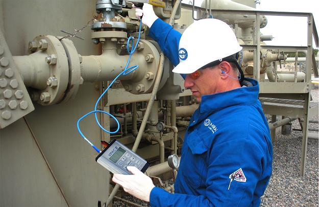
The operation of the instrument is simple. The sensor is held in contact with a flat surface, using a suitable acoustic couplant such as grease, on the valve to be tested.
The current value of the signal level (dB) is noted. This may also be stored with a single key-press in one of the 300 memory locations. If a leak is indicated by a reading greater than normal background (12 -16dB) then readings are taken on the pipework upstream and downstream of the valve.
As the signal level will be highest close to the leak and attenuate as the distance from the leak increases, these upstream and downstream figures will be lower if the valve is truly the source of the acoustic emission. The noted reading is then inserted into a PC spreadsheet along with the other relevant information:
* Valve inlet size
* Differential pressure across the valve
* Valve type
This information is used in the spreadsheet by the predictive equation to calculate the loss rates. The spreadsheet is often modified to present the loss rate in convenient units such as tonnes/year, m3/day or even product value/period.
Current experience
The VPAC II system has now been licensed for use on more than 200 sites and has proved capable of quickly surveying large numbers of valves and estimating losses from the leaking valves. In one offshore survey, 20 valves were tested and the results recorded in just over an hour. In this one small survey, leaks totalling approximately 5,100 litres/min were identified, equating to 4,500 tonnes/year. Other spectacular successes have been commonplace with the largest leak found to date being over 3,800 litres/minute from a single 24-in valve. In one refinery, a 4-inch PRV with a signal level of 85db was found, equating to 1,100 tonnes/year.
In one petrochemical plant, four 24-inch control valves were tested using VPAC. Two of these were shown to be leaking more than 2,500 tonnes/year. One oil company identified losses of $14 million from four refineries.
Not all large scale losses are due to damaged valves; leaking control valves are a common problem and these often require only a minor adjustment. One particular one-inch valve, shown to be losing £20,000/year, was fixed on the spot by simply adjusting the stop. An offshore PCV was found to be losing 500,000 mscf/day, equating to $300,000 per annum.
Troubleshooting and maintenance
The system is also being widely used for operations troubleshooting and maintenance where the value of the losses may not be the most significant feature. This is particularly true for offshore projects where the value of the gas is not high. The use of the VPAC system is now written into several maintenance procedures in the North Sea.
Initial surveys will quickly highlight the large-scale losses, which may then be dealt with. It is here that the sensitivity of the VPAC system becomes a significant advantage. Losses of as little as 1 litre/min are detectable in the field. A refinery suffering virtually no background losses is using the VPAC system to quickly track down leaks as they occur. They can achieve in a couple of hours what used to take two to three days.
Even in apparently noisy environments it is possible to detect very small leaks. This is due to the sensor design, which is very effective at rejecting vibrational noise, and advanced signal processing in the instrument. A leak of only 1.5 litres/min was detected in a relief valve in an offshore gas production platform compressor module. The background signal level on the 5131 sensor was no higher than normal even in this 'high noise' environment.
Losses also have secondary effects. One refinery user reported that hydrogen was its production bottleneck. Each tonne of hydrogen was used to make 30 tonnes of product. A control valve was identified by VPAC as losing 770 tonnes of hydrogen a year to flare. This equates to a loss of production of 23,100 tonnes per annum. These valves are now checked on a regular basis.
Of great concern to many governments is the issue of environmental damage caused by the excessive release of hydrocarbons into the atmosphere. Operators working in countries, which do not yet have strict environmental policies, will know that it is only a matter of time before they also will have to comply with the strictest emission regulations. VPAC offers a quick and simple solution to monitoring plants and effectively keeping emissions from through valve losses under control. Some company operating procedures which had required that relief valves that had lifted should be replaced (in case they had not properly re-seated) now specify VPAC to check for reseating, thus saving the cost of replacing valves after the majority of releases.
Further developments
The detection of through valve leakage using VPAC is not confined to gas systems. Where there is sufficient differential pressure to satisfy the conditions for turbulent flow, then liquid leakage can also be readily detected. The database of results on liquids has now been built up allowing quantification of through valve liquid losses. At present, work is ongoing to expand this database, which will further improve the liquid leak correlation to larger valve sizes.
A programme run offshore and in the workshop extended the procedure and correlation to very large offshore Emergency Shutdown Valves, up to 48-in diameter, in both gas and liquid service, with soft and hard seats. The purpose was to replace the statutory SI1029 test requirement, which required long period platform shutdown, with a test that could be applied rapidly during any temporary production stop, saving $400,000 per annum in the Forties field.
In addition to the detection of liquid through valve leaks, the system is also being used to detect the leaks that lead to sand erosion of valve bodies. This can also be extended to detect sand erosion at vulnerable areas in pipework.
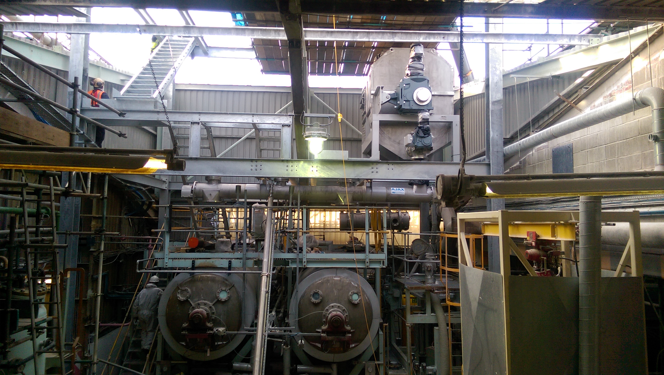
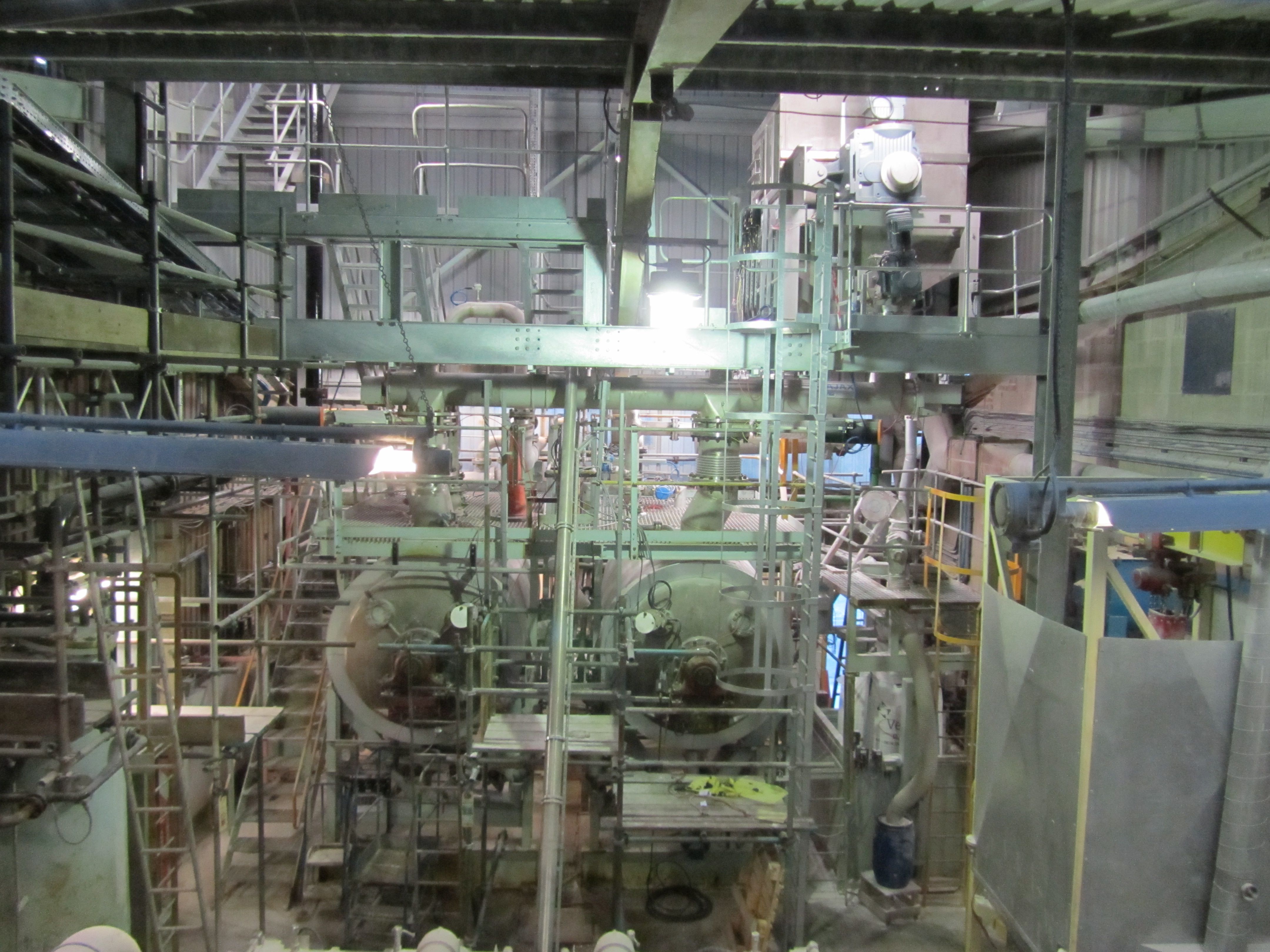
Leak detection using AE techniques is also being used successfully on boilers, where steam leak detection systems provide early warnings of steam leaks, which allows plant operators to manage the problem cost effectively, often running the plant for weeks following initial detection. These systems use sensors mounted on waveguides welded to the outside of the boiler, making installation straightforward.
Handheld AE leak detection systems are also identifying and quantifying through-valve losses of normally closed steam valves for power generation. Identifying the valves that are allowing the greatest loss is a critical tool in the financial management of these plants.
Leak detection is also being carried out in nuclear applications, where AE systems are installed on various types of nuclear reactor pipework and pressure vessels.
Conclusions
The quantification of through valve losses allows the identification of significant cost savings through loss control; prioritising of maintenance based on quantitative information; speedy and effective operations and maintenance troubleshooting; and the effective control of emissions to the environment.
Tim Bradshaw, General Manager, MISTRAS Group, UK operations.